 |
 |
 |
 |
 |
 |
 |
 |
 |
 |
 |
 |
 |
 |
| ACD / AYC / S-AYC / AT |
 |
 |
 |
|
This article is all about the ACD (Active Centre Differential) on Mitsubishi Lancer Models: Evo 7, Evo 8, Evo 9, and Evo X Note: Evo 4 only has AYC (but not ACD) I assume thats the same for Evo5, Evo6, and Evo 6.5 Trouble Codes for Mitsubishi EVO ACD:
ACD Resource Guide by Terry S – Created December 09, 2005 Table of Contents
I – Introduction to the Active Center Differential (ACD) II – Technical specifications of the ACD A – Historical overviewIII – Miscellaneous ACD information A – Parking brakeIV – Frequently Asked Questions V – Credits A. Historical overview Mitsubishi’s Active Center Differential (ACD) was first employed in 2001 on the Evolution (Evo) VII model. The ACD was to be used in support of the Active Yaw Control (AYC) carried over from the previous Evo models which controls the yaw of the car using the difference in driving and breaking forces between the two rear wheels. (1)  When the Lancer Evolution VIII model was released in the US in the spring of 2003, the Evo was outfitted without the ACD or AYC found in other markets. Instead, it was outfitted with the Viscous Coupling Unit (VCU) which distributes the torque evenly (50:50) to the front and rear wheels. This VCU was also equipped on the 2004 model year Evo in both the standard and RS models. (2) Beginning with the 2005 model year Evo VIII, Mitsubishi decided to outfit the car with the ACD unit instead of the VCU, yet still left the AYC unit out. Bastards. However, the ACD was available to all variants of the model: RS, Standard, and MR. (3) In October 2005, the 2006 model year Evo IX was released to the US market. Again, as it was with the previous model year, the ACD unit was standard equipment on all variants: RS, IX, and MR. And again, the AYC was not included. Still bastards. (4) B. What is the ACD? *NOTE* If you are unfamiliar with how a Limited Slip Differential works, then please look that up first. Howstuffworks.com, answer.com, and even EvolutionM.net have many good descriptions and diagrams available. */NOTE* The ACD is a bevel-gear type center differential with a front/rear torque distribution of 50:50. The differential is controlled by an electrically controlled hydraulic multi-plate clutch. For greater dependability, the clutches were made from steel. (1) The differential itself is located inside the transmission housing while the ACD clutch pack is located inside the transfer-case. (http://forums.evolutionm.net/attachment.php?attachmentid=70736 Light green and dark blue sections in this PDF by SuperHatch (5)) The ACD ECU is located to the right side of the glove box, behind the passenger side kick-panel. (6) The ACD hydraulic unit is housed in the engine compartment and regulates the hydraulic pressure of the multi-plate clutch within the range of 0 to 145 psi. The maximum limited-slip torque of the multi-plate clutch is about three times that of a conventional VCU. Translation: 3 times the grip transferred to the wheels that need torque. (3) There are many different sensors used by the ACD when determining how it will control the center differential. ABS input, steering wheel angle, throttle opening, wheel speeds, and longitudinal and lateral movements of the vehicle are constantly measured by the ACD. Additionally, the driver can select how the ACD will perform by selecting one of three different modes from a switch in the cabin: Tarmac, Gravel, or Snow. (7) (1) (3)   (Both pictures from www.mitsubishicars.com)
When comparing the USDM version of the ACD to that of other markets Evo’s, the difference lies with the USDM ACD not connecting to an AYC control unit & hydraulic system since the car does not have them. (1) C. How the ACD works In short, the ACD unit hydraulically controls the limited-slip locking state of the center differential which ranges between full locked, full open, and every point in between these two states. It calculates what the optimum locking amount would be using real-time input from the previously mentioned sensors and which ACD mode is selected. The ACD is extremely fast in operation, bettering the performance of the standard VCU and Viscous units. (3) (7) When the car is accelerating or decelerating rapidly, the ACD begins to engage the limited-slip locking on the differential. The harder you accelerate or decelerate, the more it locks. This is done to provide maximum lateral stability and wheel traction. (3) (8) The ACD allows the differential to operate in more of a free state when steering movements are made. When turning, the wheels in the front have to travel a further distance than the wheels in the rear. This is because the wheels in the front travel using a larger turning radius than the rear wheels as you can see from this picture. (turning radius.gif) So in order for smooth turning, the center differential needs to become open to allow for the front set to turn at a different speed. If you were to leave the center differential locked, the wheels would skip and skid badly. (1) (3) 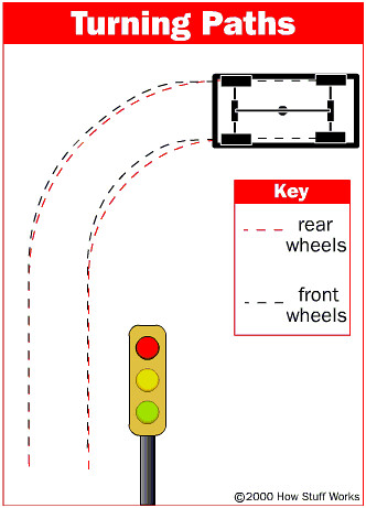  (Picture from www.howstuffworks.com and www.mitsubishicars.com)
If the front wheels are spinning faster than the rear wheels, then the ACD begins to lock the clutches up. If the amount of force exerted by the front wheels is less than the amount the clutches resist, then the slip is stopped and both front and rear spin at the same speed. However, if the force the clutches can resist is less than the force exerted by the slipping set of wheels, then the wheels will slip, but only by how much remaining force the slipping wheels overpowered the clutches with. (1) (9) D. How the Tarmac/Gravel/Snow switch influences the ACD Despite popular belief, this switch DOES NOT change the torque split. The differential is geared at 50:50 and cannot be changed by the push of a button. What this switch actually does is quite simple. Each setting determines how long the ACD will delay in freeing the center differential after a steering input is made. In addition, it will determine how much locking force the ACD will exhibit on the clutch pack and center differential. (10) (11) Tarmac is the setting to be used in dry, paved conditions. In this setting, the ACD will almost immediately allow the center differential to go into a free state upon detecting a steering input. Additionally, this mode provides the strongest limited-slip clamping force of the three modes. (7) (12) Gravel is the setting designed for wet or loose roads. In this setting, the ACD will delay in freeing the center differential for a moment (possibly 2-3 seconds). Of the three modes, this one has the second strongest clamping force. (7) (12) Snow is the setting designed for, you guessed it, snow. In this setting, the ACD will delay in freeing the center differential for much longer than the other two settings (possibly 4-5 seconds). Of the three modes, this one also provides the least amount of clamping power. (7) (12) III. Miscellaneous ACD information
A. Parking brake As stated in the owners manual and in several places around the internet, when you engage the parking brake, the ACD is disengaged to prevent damage to your drivetrain and the ACD unit. The reason this would cause damage is because if you were to have an engaged ACD attempting to lock the center differential then you yank on the parking brake stopping the rear set of wheels from spinning, you are forced to attempt to overpower the ACD unit from keeping the rear wheels from spinning. This puts a tremendous amount of strain on the ACD clutches, the ACD hydraulics, center differential and your brake system. (7) (12) B. ACD interference with aftermarket downpipes Yes it is true that some aftermarket downpipes will not initially fit. This is typically because the manufacturer created the downpipe using either an 03 or 04 model for fitment. Since those model years did not contain the ACD unit, the transfercase was smaller and more compact. But starting with the 05 model year, the transfercase contained the clutch pack which widened the transfercase housing. Most manufacturers have either solved this problem or offer downpipes exclusive for the 05-06 model years. (13) C. Upgrading the ACD While it is possible to upgrade the ACD ECU for the Evo VII/VIII/IX in other markets, at the time of this writing, there are NO ECU UPGRADES available for the USDM version of the VIII or IX. Reason being is that the ACD unit found in other markets also doubles as the AYC control unit. Since we do not have the AYC in our version, the aftermarket units would probably freak-out and not work. I have found no evidence of someone trying to equip a USDM Evo with an aftermarket ECU however. (14) (15) D. ACD unit fault – 3 solid lights When your ACD unit has all three lights on at the same time (other than at startup), this means your car is reporting back to Mitsubishi headquarters that your warranty should be voided… Just kidding. As stated in your owners manual, this denotes some kind of error in the unit and it needs to be serviced. To service the ACD you need a very special, and very expensive tool from Mitsubishi. This tool is used to engage the ACD pump to bleed the lines. You may run into this issue if you are changing out your transfercase. (6) E. Upper Intercooler Pipes There are reports on the internet that some have had issues with installing intercoolers & upper intercooler piping. The issue lies with one of the ACD oil lines getting in the way. Most people report no issue or only a slight fitment issue solvable by slightly moving or bending the line out of the way. (16) (13) F. Changing the front/rear torque split There are rumors of a 35/65 center differential made by Cusco, but it does not appear to be available for the USDM market Evo’s. (15) G. Strength of the ACD unit The center differential itself appears to be similar to the version in the 03-04 model years, but it is connected to the ACD clutch pack instead of the VCU. Since there are hydraulics & electronics involved with the system, some have expressed concern that something is bound to show signs of weakness. At the time of this writing however, there have been no obvious weak points in the ACD system. (17) IV. FAQ’s
http://www.motec.com.au/mdc/mdcfeatures/ ACD Wiring: Mitsubishi JDM Evo ACD circuit board top - Click image for High Res 2MB image download 
some main content here
24 - ground for G-sensor (both) 23 - G-sensor long 11 - G-sensor lat 37 - brake light warning 31 - power backup <== 17 - power source <== 38 - brake switch 47 - ACD MODE switch 40 - TALMAC LED 52 - GRAVEL LED 51 - SNOW LED 36 - connection with Engine ECU pin 87 39 - TPS 16 - electric pump relay 43 - 5V for pressure sensor 32 - input pressure sensor 10 - ground for pressure sensor 1 - proportional valve for ACD control 19 - ground for left front wheel speed sensor 20 - ground for right rear wheel speed sensor 21 - ground for left rear wheel speed sensor 22 - ground for right front wheel speed sensor 6 - signal for left front wheel speed sensor 9 - signal for right rear wheel speed sensor 8 - signal for left rear wheel speed sensor 7 - signal for right front wheel speed sensor 33 - steering wheel sensor 34 - steering wheel sensor 44 - steering wheel sensor 50 - ground <== 42 - ground <== 26 - ground <== 35 - OBD port, pin 7 46 - OBD port, pin 1 ACD with AYC 31 - power backup (apply 12v) 13 - power source (apply 12v) 38 - brake switch (apply 12v = on) (also goes to ABS) 23 - G-Sensor Longitudinal (also goes to ABS pin 25) 11 - G-Sensor Lateral (also goes to ABS pin 14) 47 - ACD Mode Changeover switch (apply 12v = on) 40 - Tarmac LED Light 52 - Gravel LED Light 51 - Snow LED Light 39 - Throttle Position Sensor 36 - goes to EFI ecu pin 87 39 - Brake Warning LED Light (park brake LED) 49 - connects to ABS ecu pin 3 7 - Right Front Wheel Speed Sensor (comes from ABS ecu pin 21) 8 - Left Rear Wheel Speed Sensor (comes from ABS ecu pin 20) 6 - Left Front Wheel Speed Sensor (comes from ABS ecu pin 32) 9 - Right Rear Read Wheel Speed Sensor (comes from ABS ecu pin 18) 16 - Electric Pump Relay 43 - 5v for Pressure Sensor 32 - Input Pressure Sensor 10 - Ground for Pressure Sensor 1 - Proportioning valve for ACD control 3 - Proportioning valve for AYC control 15 - Direction valve - Left 3 - Direction valve - Right 33 - Steering Wheel Sensor 34 - Steering Wheel Sensor 44 - Steering Wheel Sensor 42 - Ground (negative) 26 - Ground (negative) 35 - OBDII Port, pin7 46 - OBDII Port, pin1 EVO 5 AYC PINOUTS:  EVO6 AYC only has 8x2 pins on the right. 39 Battery Backup 31 Ignition 46 ground 26 ground 10 OBDII pin 1 23 OBFII pin 7 Reflashing Evo7/8/9 ACD ECU PINOUT  EvoScan ACD Datalogging and Actuators:  Pin13 12 Volt DC (11.8V to 14.4V is ok)
Pin31 12 Volt DC (11.8V to 14.4V is ok) Pin42 Ground (negative) Pin25 Reflash line from OpenPort 2.0 12pin Adapter Pin35 OBDII pin 7 (OpenPort 2.0) Pin46 OBDII pin 1 (OpenPort 2.0) 12 Volts DC Power to OBDII pin 16 (OpenPort 2.0) Ground (negative) to OBDII pin 4 (OpenPort 2.0)   EVOX ACD ECU: MH8104F (144pin M32R)  EvoX ACD Pin Plug Layout confirmed same as Evo9. Actual EvoX ACD pin labels unknown, presumed similiar as Evo9 above. Youtube video of EvoX ACD in action Evolutionm.net Thread discussion on EvoX ACD openECU reprogramming. Quote from Acamus: I have been browsing the Renesas site for quite a while querying for 144 pin processors and the only model that I have found to have correct pin assignment was 32176 or 32192. So it seems its m32r type of processor.  MMCFlash supports read/write EvoX ACD MH8104F  Evo7/8/9 ACD discussion on the forum https://www.evolutionm.net/forums/ecuflash/473547-break-thru-reading-acd-ecu-ecuflash-40.html#post11875715 SOURCE: ROB-80E JUNE 2019: That light bulb moment when everything starts to make sense! I found a link to Longitudinal G into the ACD control section. It eventually gets assigned to address F016. The two tables in the ACD control section that use this address as axis data is F and G tables. Merlin had a long time ago posted the mathematical process the ROM goes through with different tables within the ACD section. For most part he has been correct and essentially it comes down to (and these are in order as they are processed within the ROM): P x J (J tables aren't present in Evo 7 roms. Also note, the P table is the big 9x36 table which was thought to be AYC) D x E F A x B G x C (H table is also tacked on here, but there's quite a bit of constant data manipulated with it. Given that the values are 1, i'm going to ignore it as it has no effect on the result). The only map I'm still not sure exactly what it does is the P map. The values don't make sense as a lockup adder. When reading the design concept documentation and looking at the block diagram above, I think it has the possibility of being: - sets the target value of the target body posture - varies the ratio between the Target and Actual body postures, or - varies the ratio between the Feedback and Feedforward control sections. It's worth noting that there are a number of things that could do any of the above, and are specific to T,G or S modes too (P map is not). Anyway, back on track....lets add some names to the equations. P = ACD Main Map J = ACD Main Map coefficient (reduces the effect of the main map with reference to vehicle speed) D = Front to Rear wheel speed delta (ACD lockup adder) E = D map coefficient (reduces the amount of ACD lock because of F/R speed difference with reference to vehicle speed) F = Acceleration G-force (ACD lockup adder) A = Throttle lockup adder (3D table which can be adjusted with reference to vehicle speed) B = Throttle coefficient (reduces the amount of ACD lock because of throttle input with reference to steering angle) G = Braking G-force (ACD lockup adder) C = Braking coefficient (reduces the amount of ACD lock because of braking g-force with reference to steering angle). H = Steering angle velocity coefficient (reduces the amount of ACD lock with reference to steering wheel speed...values are 1 in 8/9 ROMS, so this has NIL effect). Sabin, based on this...there's your Accel/Decel tables.   |
|||||||||||||||||||||||||||||||||||||||||||||||||||||||||||||||||||
| Last Updated on Tuesday, 11 June 2019 12:37 | |||||||||||||||||||||||||||||||||||||||||||||||||||||||||||||||||||


Copyright 2009 (c) Limitless Designs LLC.